Complete Guide to Electrical Symbols and Abbreviations
What are electrical symbols, and what do they mean? Where are they placed on a floor plan, and what are the regulations for placing them? Here's everything you need to know about electrical plans.


Electrical symbols help visualize where electrical elements will be placed in a building. Using electrical symbols on a floor plan is the perfect way to do this. You can use these symbols to show where any electrical feature will be placed, from general lighting fixtures, specialty and decorative lighting, power outlets and receptacles, switches and controls, and so much more.
They are universally recognized, so anyone working on a project can understand them.
It might sound intimidating, but don't worry! We'll cover everything in this post, making it easy to understand. After this, you'll be able to draw electrical plans with confidence.
1. Lighting

Lighting can be separated into two different categories: general lighting and specialty and decorative lighting.
General lighting includes ceiling fan and light, pendant fixture light, surface ceiling light, wall light, surface wall lights, recessed wall light, and outdoor light.
Specialty and decorative lighting includes floor light, step light, and LED strip light.
Light fixtures are easy to spot on an electrical floor plan with their yellow signaling light. However, there are a few exceptions, such as luminaire lights and LED lights. Luminaire lights are illustrated with a black x, and LED lights are illustrated with two black parallel stipulated lines.
2. Power Outlets & Receptacles
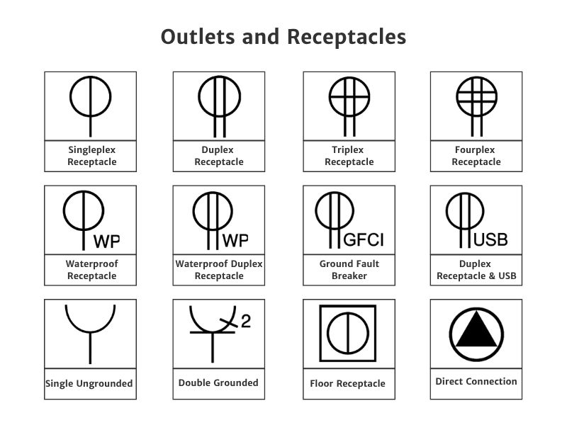
The symbols for electrical outlets and receptacles are used to show the placement of power outlets and receptacles.
For example, a singleplex receptacle is a circle with a line cutting through the middle and coming out on the bottom of the circle. A duplex receptacle is the same as a singleplex receptacle but has two lines.
3. Switches & Controls
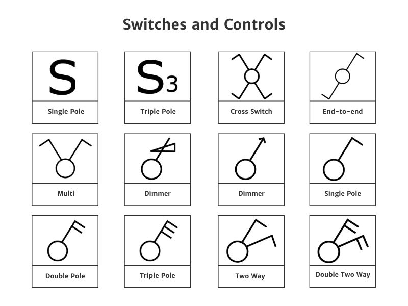
You don't just need to show the placement of light fixtures, but also where you can turn on the light, which is where the switches and controls come in. These handy symbols will show where and what kind of switches and controls that need to be installed.
Switches are illustrated in various ways, but most of them have the circle in common. The exceptions are the symbols for single pole and triple pole switches. These are illustrated with a capital "S" and a capital "S" with a smaller number "3" next to the "S".
4. Electrical Boxes & Junctions
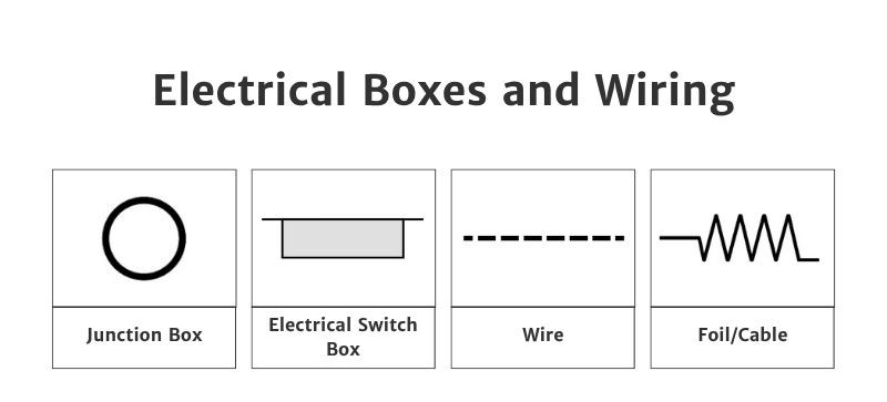
Just as important are electrical boxes and wiring. These show where all the electrical wires will be, the electrical switch box, and junction box.
Switch boxes mark where you’ll control lights or outlets, while junction boxes show where wires connect behind the scenes. These symbols on your floor plan help people understand how power flows through the space and where key electrical access points are located.
A junction box is drawn as a circle, and a wire is a stipulated line.
5. HVAC & Ventilation
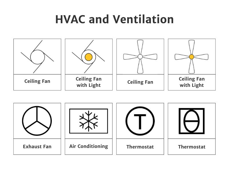
HVAC (Heating, Ventilation, and Air Conditioning) includes heating systems, ventilation systems, air conditioning units, and thermostats.
The difference between the two ceiling fans with light is that one is drawn with a circular swirl with three curved lines extending outwards, suggesting motion or air flow, with a solid yellow circle in the center indicating a light fixture. The other ceiling fan with light is drawn as a traditional 4-blade fan shape with symmetrical blades extending from a central hub. Inside the hub is a yellow circle representing the light fixture.
On a floor plan, these symbols show where warm or cool air will enter and exit a room. They also indicate where air will circulate, helping you plan for comfort, airflow, and energy efficiency.
6. Detection & Alarm Systems
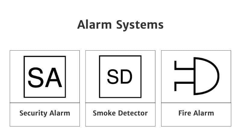
Here to keep any building safe are the symbols for alarm systems, including security alarms, smoke detectors, and fire alarms. These symbols show where safety devices are installed, so you can plan for full coverage throughout your space.
Knowing their placement helps you avoid blocking sensors and ensures you meet safety requirements during your design. The symbols for security alarms and smoke detectors are easy to remember, as they are both square with letters inside representing what they are.
The security alarm is drawn as a square with the letters "SA" inside it. The smoke detector is drawn as a square with the letters "SD" inside it.
Regulations
There are a few regulations to consider when placing electrical symbols on a floor plan. They should follow these regulations for correct placement when installing electrical elements in a build.
General regulations include:
- No floor wiring: Branch circuit conductors (electrical lines) should only be routed through walls, ceilings, or under floors as concealed wiring, never on top of the floor.
- Labeling: Electrical floor plans should clearly show locations of switches, outlets, lighting fixtures, and distribution panels.
- Compliance: Always check for additional local amendments to the NEC, as some municipalities or states have stricter or extra requirements.
💡The National Electrical Code:
In the USA, the National Electrical Code (NEC) governs the placement of electrical elements on floor plans. This provides standardized rules for safety, accessibility, and practical use.
Outlet placements (receptacles) by room:
- Living areas: Must be placed so that no point along a wall is more than 6ft from a receptacle. This prevents excessive use of extension cords and gives convenient access to power.
- Wall requirements: Any wall section wider than 2ft must have at least one outlet. Wall receptacles should not be farther than 12ft apart.
- Windows and corners: Place outlets beside windows, particularly if curtains or window automation are used, and at the bottom of staircases for vacuum or other uses.
- Bathrooms: Outlets must be no more than 3ft from the outside edge of a sink. and are typically installed above countertops.
- Kitchens: NEC requires that no point along the kitchen countertops is more than 24 inches from a receptacle.
Switch placement
Switches should be installed near room entryways and in locations that are easy to reach, at standard heights (usually around 48 inches above the floor).
Also, for accessibility, make sure switches are not in hard-to-reach areas and consider the furniture layout and room usage.
Electrical Symbols Abbreviations
Here are some common electrical symbols abbreviations used in schematics, wiring diagrams, and electrical documents:
| Abbreviation | Meaning |
| AC | Alternating Current |
| DC | Direct Current |
| V | Volt |
| A | Ampere |
| mA | Milliampere |
| kA | Kiloampere |
| W | Watt |
| VA | Volt Amp |
| Ω | Ohm |
| Hz | Hertz (frequency) |
| kV | Kilovolt |
| AWG | American Wire Gauge |
| CU | Copper |
| AL | Aluminum |
| CB/C/B | Circuit Breaker |
| ATS | Automatic Transfer Switch |
| AFCI | Arc Fault Circuit Interrupter |
| G | Conductance |
| L | Inductance (Henry) |
| C | Capacitance (Farad) |
| CT | Current Transformer |
| PT | Potential Transformer |
| DB | Decibel |
| BTU | British Thermal Unit |
| CATV | Cable Television |
| Φ | Phase |
| ELV | Extra-Low Voltage |
| ELCB | Earth Leakage Circuit Breaker |
| EMC | Electromagnetic Compatibility |

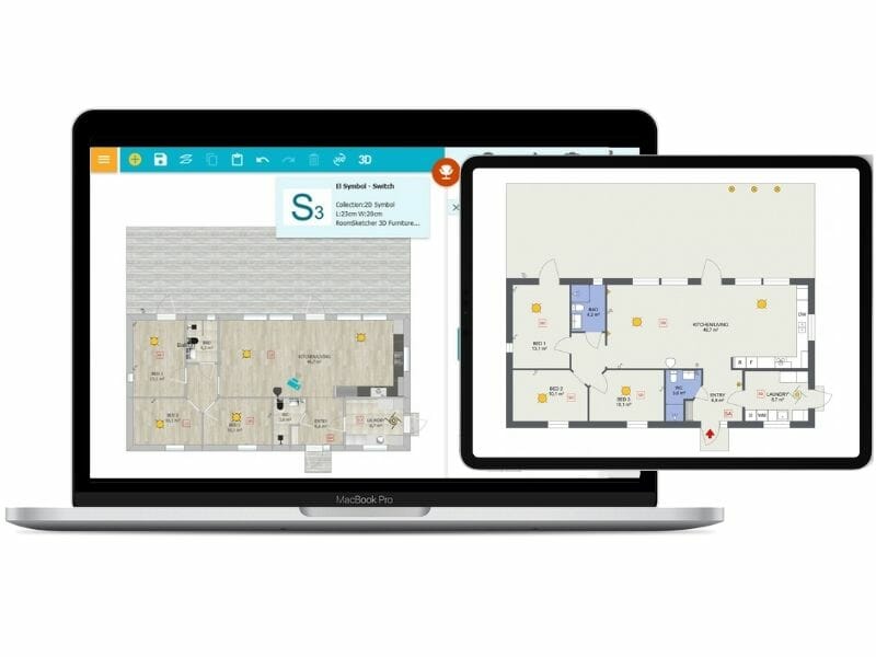
Make Electrical Plans With RoomSketcher
Ready to start? Upgrade your electrical plans with a paid RoomSketcher subscription and get other features like:
- Use advanced measurements and Total Area
- Generate, download, and print high-quality floor plans
- Order floor plans at a discount
- Get an expanded furniture library and use Replace Materials
- Take 3D Photos, 360 Views and use Live 3D
Recommended Reads
How to Draw an Electrical Plan With RoomSketcher
Learn how to create precise electrical plans using RoomSketcher. Design and visualize your electrical system with ease.

Electrical Plan Examples and Templates to Kick-Start Your Project
Transform your project with electrical plan examples and templates. Streamline your planning process for success. Explore now!

The Ultimate Guide to Blueprint Symbols
Blueprint symbols might look complex, but they're actually a straightforward way to communicate design ideas. Let's take a look at common symbols and how they're used.