The Ultimate Guide to Blueprint Symbols
Blueprint symbols might look complex, but they're a straightforward communication method. Let's take a look at common symbols and how they're used.


One of the most important aspects of reading blueprints is understanding their symbols. These symbols convey everything from the layout of a building to the placement of electrical outlets and plumbing fixtures.
In this post, we’ll break down some of the most common blueprint symbols—what they mean, why they matter, and how they’re used. From orientation compasses to structural elements and landscaping details, you’ll learn to read blueprints like a pro.
What are Blueprint Symbols?
Blueprint symbols are standardized marks and signs used on architectural and engineering drawings to represent various building elements.
By using these symbols, professionals can save space on drawings and ensure everyone is on the same page. This not only reduces misunderstandings and errors but also helps projects run more smoothly.
From doors and windows to electrical outlets and plumbing fixtures, each symbol has a specific meaning. Together, they help turn a concept into a real building. By standardizing these symbols, professionals can work more efficiently and accurately, ensuring projects are completed to a high standard.
Orientation Compass

When you start working with blueprints, one of the first things to catch your eye is the orientation compass. It's a key symbol that helps you understand how the building sits on the land and faces the world.
Usually, you'll see it as an arrow or a simple compass rose, often with an "N" to show you which way is north. Even in complicated drawings, it's designed to be clear and easy to spot.
💡 Did you know?
The "north" indicated on a blueprint might not always align with True North (the actual magnetic north).
Architects often use "Project North," which is a reference point chosen for the convenience of the drawing.
This means that the orientation of the building on the blueprint might differ slightly from its actual orientation in relation to True North.
Structural and Architectural Symbols

Windows
Windows are often shown as empty rectangles breaking into wall lines. More detailed drawings may include two parallel lines for the frame and a third line for the glass.
Doors
A break in the wall line represents doors. An arc indicates the swing direction: inward for doors opening into a room and outward for doors opening away from a room.
Beams and Columns
Beams are depicted as thick parallel lines, with the space between them representing the beam's width. Columns are shown as squares or rectangles, sized according to their cross-sectional dimensions.
Electrical symbols
Electrical symbols are a key part of blueprint drawings, representing essential components like light fixtures, outlets, and switches. These symbols help ensure that electrical systems are installed correctly and safely, making them a vital part of any construction project.
Related: How to Draw an Electrical Plan With RoomSketcher
Light Fixtures

Light fixture symbols help differentiate between types of lighting. Ceiling lights, for example, are often drawn as circles representing the light fixture itself. Solid lines extending from the circle show the direction of light or the fixture's coverage area.
Meanwhile, wall lights are typically drawn as a half-circle or a large "D" shape. This distinct symbol helps distinguish them from ceiling fixtures and clarifies where they're mounted.
Outlets

Outlet symbols are used in blueprints to represent the locations and types of electrical outlets throughout a building. These symbols help ensure that power sources are placed correctly and meet the design's needs.
A singleplex receptacle outlet is typically drawn as a circle with a single line connecting it to the wall. While a duplex receptacle outlet is shown as a circle with two parallel lines.
Specialized outlets, such as those for appliances or USB ports, have labels to distinguish them, such as "WP" for waterproof.
Switches

Switch symbols in electrical diagrams represent different types of switches and their functions.
A single-pole switch is typically shown as an "S," making it easy to identify. For a triple-pole switch, the symbol is an "S" with a "3" next to it, indicating its three poles.
Dimmer switches are represented by a circle with an arrow coming out of it or by a circle with a line and a triangle.
An end-to-end switch is depicted as a circle with two bent lines extending outward from opposite sides.
Plumbing Symbols

When it comes to plumbing, symbols play a big role in helping us visualize fixtures and appliances on bathroom and kitchen floor plans. Toilets and bathtubs are usually drawn to look like the real thing, making them easy to spot.
Showers are often represented by triangles with lines coming out, which gives you a sense of the water spray from the shower head.
For appliances, water heaters are shown as a circle with "WH" marked on it, while washing machines are depicted as squares or rectangles labeled "WM."
HVAC Symbols
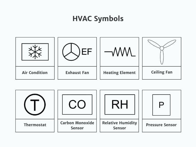
HVAC symbols are used to show important parts of heating, ventilation, and air conditioning systems on blueprints.
For example, air conditioning units are usually drawn as rectangles with a snowflake inside, while heating elements are shown as zigzag lines representing the heating coils.
Thermostats are marked as small circles with a 'T' inside, making it easy to spot where the temperature is controlled. Pressure sensors are shown as circles with a 'P' inside, sometimes with arrows to show how pressure is measured.
Related: How to Make an HVAC Floor Plan With RoomSketcher
Fixed Installations

Kitchen appliances are shown as simple shapes with labels. Refrigerators look like rectangles, sometimes with a curved front for the door. They're often marked with "R" or "REF."
Stoves are rectangles, too, but with circles inside for the burners. A four-burner stove has four circles, while a two-burner has two. You might see "S" or "STOVE" written next to it.
Dishwashers are squares or rectangles labeled "DW" or "DISHWASHER."
Exterior symbols

Exterior symbols help us visualize outdoor spaces. For example, pools and hot tubs are drawn to match their shape. If they're rectangular, the symbol will be a rectangle; if they're curved, the symbol will have wavy edges.
Plants are shown as clusters of leaves that resemble their real-life shape.
Pathways are illustrated to show the material used. For example, a brick path might be drawn as small rectangles, giving you an idea of how it will look.
Fences are drawn using two parallel lines with short marks at regular intervals. These marks show where the fence posts will be, helping you understand the fence's layout.
Make Your Own Blueprints with RoomSketcher
Ready to streamline your blueprinting process and save time?
With RoomSketcher, you can create professional-looking blueprints in under an hour even without CAD training or technical drafting experience. This means you can get started right away!
- Use the intuitive interface to create blueprints quickly
- Eliminate the need for expensive drafting services
- Visualize and adjust your designs with ease
Want to Learn More?
5 Tips on How to Draw a Blueprint by Hand
How do you draw a blueprint by hand quickly and efficiently? Discover the top tips on how to create an accurate blueprint using just pen, paper, and a laser measurer.

How to Choose a Floor Plan: 5 Essential Steps
Stuck trying to choose a floor plan and worried you'll make the wrong choice? Building or buying a home is a huge investment, and the layout is crucial. We're here to help you confidently navigate the process.

The Complete Guide to Reading Blueprints Effectively
Blueprints can seem overwhelming, but you don’t have to be an engineer to understand them! Learn how blueprints are structured, what the symbols mean, and how to read them effectively.