Complete Guide to Electrical Symbols and Abbreviations
What are electrical symbols, and what do they mean? Where are they placed on a floor plan, and what are the regulations for placing them? Here's everything you need to know about electrical plans.

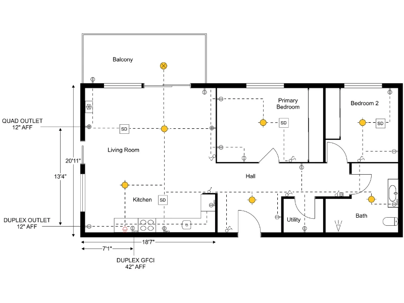
Electrical symbols show where lighting, outlets, switches, and other electrical elements are placed in a building. On a floor plan, these symbols make it easy to understand how the electrical layout works and where each feature belongs.
Because these symbols follow standard conventions, anyone involved in the project can read the plan and understand the layout. They’re a key part of how you create an electrical plan, making sure everything is placed clearly and works as intended.
In this guide, we’ll walk through the most common electrical symbols and explain what they represent.
1. Lighting
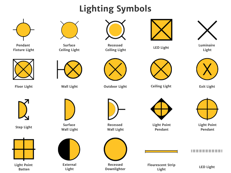
Lighting symbols on an electrical plan usually fall into two categories: general lighting and specialty or decorative lighting.
General lighting includes fixtures that light an entire space. Common examples are ceiling fans with lights, pendant lights, surface ceiling lights, wall lights, recessed wall lights, and outdoor lights.
Specialty and decorative lighting highlights specific areas or adds visual detail. This group includes floor lights, step lights, and LED strip lights.
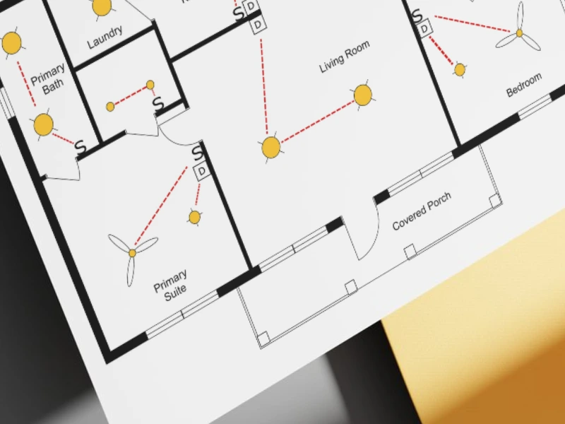
On many electrical plans, lighting fixtures are shown with a yellow indicator to make them easier to spot. However, they can also be displayed in black and white depending on the drawing style.
Recommended article: How to Make a Lighting Plan in 7 Steps
2. Outlets
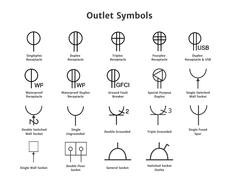
Electrical outlet and receptacle symbols show where power points are placed on an electrical floor plan.
For example, a simplex receptacle is typically shown as a circle with a single line running through the center and extending downward. A duplex receptacle uses the same symbol but has two vertical lines instead of one.
Some symbols also include labels or markings to indicate special features. For instance, GFCI outlets are marked with the letters “GFCI,” while USB outlets show a small USB indicator next to the receptacle symbol.
3. Switches
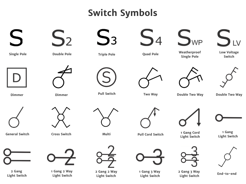
Switch symbols show where lights and other electrical devices are controlled on a plan. They indicate both the location of the switch and the type of control used.
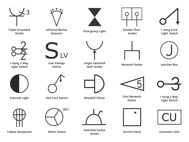
Many switch symbols include a circle to represent the switch location. Others use letters or small markings to indicate the switch type. For example, a single-pole switch is often shown with a capital “S”, while a triple-pole switch uses a capital “S” with a small “3.”
These symbols help electricians and designers understand how lighting and electrical devices are controlled throughout the space.
4. HVAC
HVAC symbols show where heating, ventilation, and air conditioning elements are placed in a building. These symbols help identify components such as ceiling fans, exhaust fans, air vents, and thermostats.
On a floor plan, HVAC symbols indicate how air moves through a space and where temperature controls are located. This helps ensure proper airflow, comfort, and efficient heating or cooling throughout the building.
Ventilation
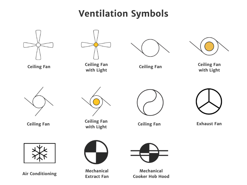
On a floor plan, ventilation symbols help indicate how air moves through a space. For example, ceiling fans are used to circulate air within a room, while exhaust fans and mechanical extract fans remove stale or humid air from areas like bathrooms and kitchens.
You may also see symbols for air conditioning units and cooker hood extraction, which help control temperature and remove heat, smoke, or odors. Showing these elements on a plan makes it easier to coordinate airflow, comfort, and equipment placement throughout the building.
Heating and Water
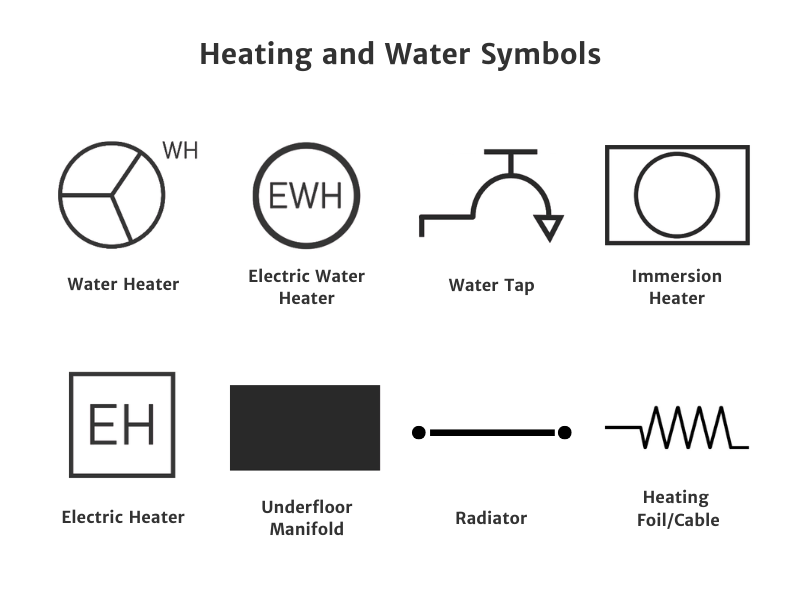
Heating and water symbols show where equipment related to hot water and space heating is located. These symbols may represent elements such as water heaters, electric heaters, radiators, and underfloor heating systems.
On a floor plan, they help indicate how heat and hot water are distributed throughout the space and where key system components are installed.
Thermostats
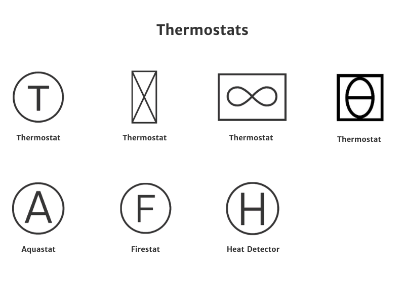
Many thermostat symbols are drawn as a circle with a letter inside that indicates the device type. For example, a “T” typically represents a thermostat, while other letters may indicate related controls such as an aquastat, firestat, or heat detector.
However, basic thermostats can also be shown in different ways depending on the drawing style or standard used. Some plans use alternative shapes or simplified symbols, but they all represent the same function.
5. Safety and Security Systems
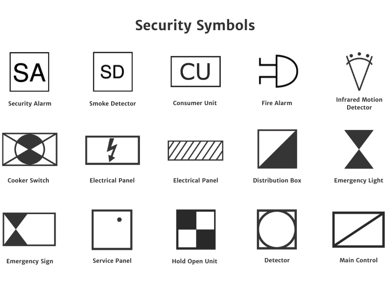
Symbols for security and safety systems show where protective devices are installed in a building. These may include security alarms, smoke detectors, fire alarms, emergency lights, and electrical control units.
Placing these elements on a plan helps ensure proper coverage throughout the space. It also helps you avoid blocking sensors and makes it easier to meet safety requirements during the design process.
Some symbols use letters to represent the device. For example, a security alarm is drawn as a square with the letters “SA”, while a smoke detector is shown as a square with the letters “SD.” Other symbols use simple shapes to represent panels, emergency lighting, and control units.
6. Data, Telephone, and TV
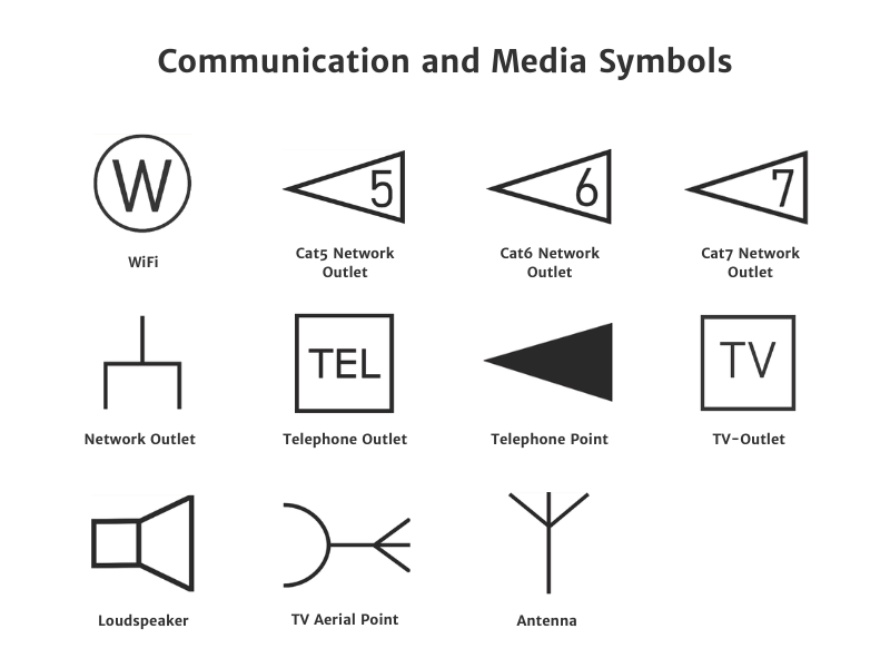
Communication and media symbols show the location of data, telephone, and television connections.
On a floor plan, you may see symbols for Wi-Fi access points, network outlets, and Cat5, Cat6, or Cat7 data connections. These indicate where wired internet connections are available.
You may also see symbols for telephone outlets, TV outlets, antennas, and aerial points, which show where communication or media equipment can be connected.
7. Machinery
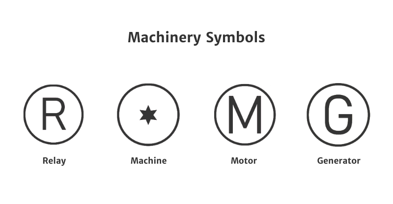
Machinery symbols represent electrical or mechanical equipment connected to a building’s systems. These may include components such as relays, motors, generators, or other types of machinery.
Most of these symbols are drawn as a circle with a letter or simple symbol inside that identifies the equipment. For example, “R” represents a relay, “M” indicates a motor, and “G” represents a generator.
8. Doorbells
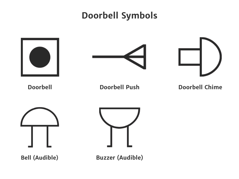
Doorbell symbols show where doorbell systems and audible alerts are installed in a building. These symbols may represent elements such as doorbell push buttons, chimes, bells, and buzzers.
On a floor plan, they help indicate where visitors can trigger a doorbell and where the audible signal is located inside the building. This makes it easier to plan entry points and ensure the alert can be heard throughout the space.
Electrical Plan Regulations and Guidelines
When placing electrical symbols on a floor plan, it’s important to follow building and electrical regulations. These rules help ensure electrical systems are safe, accessible, and practical to install.
While requirements vary by location, most projects follow a combination of national electrical codes and local building regulations:
Wiring placement
Electrical wiring is typically routed through walls, ceilings, or beneath floors as concealed wiring. It should not run across the surface of finished floors.
Clear labeling
Electrical plans should clearly show the location of switches, outlets, lighting fixtures, and distribution panels so installers can easily understand the layout.
Local code compliance
Always check local building regulations. Many regions adopt national standards but add their own requirements.
💡The National Electrical Code:
In the USA, the National Electrical Code (NEC) governs the placement of electrical elements on floor plans. This provides standardized rules for safety, accessibility, and practical use.
Outlet Placement
Living areas
Outlets must be placed so that no point along a wall is more than 6 feet from a receptacle. This reduces the need for extension cords.
Wall sections
Any wall section wider than 2 feet requires at least one outlet. Receptacles should generally be spaced no more than 12 feet apart.
Bathrooms
At least one outlet must be installed within 3 feet of the sink. These outlets are typically placed above the countertop and must include GFCI protection.
Kitchens
Kitchen countertop outlets must be spaced so that no point along the wall line is more than 24 inches from a receptacle.
Switch placement
Light switches are usually installed near room entry points so lights can be easily controlled when entering or leaving a space.
They are typically placed at a standard height of about 48 inches above the floor, although accessibility requirements may vary depending on local building codes.
Electrical Abbreviations
Here are some common electrical abbreviations used in schematics, wiring diagrams, and electrical documents:
| Abbreviation | Meaning |
| AC | Alternating Current |
| DC | Direct Current |
| V | Volt |
| A | Ampere |
| mA | Milliampere |
| kA | Kiloampere |
| W | Watt |
| VA | Volt Amp |
| Ω | Ohm |
| Hz | Hertz (frequency) |
| kV | Kilovolt |
| AWG | American Wire Gauge |
| CU | Copper |
| AL | Aluminum |
| CB/C/B | Circuit Breaker |
| ATS | Automatic Transfer Switch |
| AFCI | Arc Fault Circuit Interrupter |
| G | Conductance |
| L | Inductance (Henry) |
| C | Capacitance (Farad) |
| CT | Current Transformer |
| PT | Potential Transformer |
| DB | Decibel |
| BTU | British Thermal Unit |
| CATV | Cable Television |
| Φ | Phase |
| ELV | Extra-Low Voltage |
| ELCB | Earth Leakage Circuit Breaker |
| EMC | Electromagnetic Compatibility |

Make Electrical Plans with RoomSketcher
Create clear electrical plans without complex CAD software. Start with your floor plan, place outlets, switches, and lighting, and adjust the layout until everything fits the space.
When you're ready, generate a professional plan that’s easy to share with electricians, contractors, or clients.
Recommended Reads
How to Draw an Electrical Plan with RoomSketcher
Learn how to draw an electrical plan step by step. This guide shows how to place lighting, outlets, and switches clearly on your floor plan so the layout is easy to understand and share.

Electrical Plan Examples to Kick-Start Your Project
Electrical plans show where outlets, switches, lighting, and other electrical elements should be placed within a space. In this article, you’ll find a collection of electrical plan examples for different rooms and building types, along with practical tips to help you plan your own layout.
How to Create a Reflected Ceiling Plan
A reflected ceiling plan helps you organize everything that happens above a room. It shows where lighting, ventilation, and other ceiling elements should be placed so the layout works both visually and technically.