How to Read an Electrical Floor Plan
Learn how to read an electrical floor plan with confidence. This guide explains the symbols, labels, and connections used to show lighting, switches, outlets, circuits, and other electrical systems.
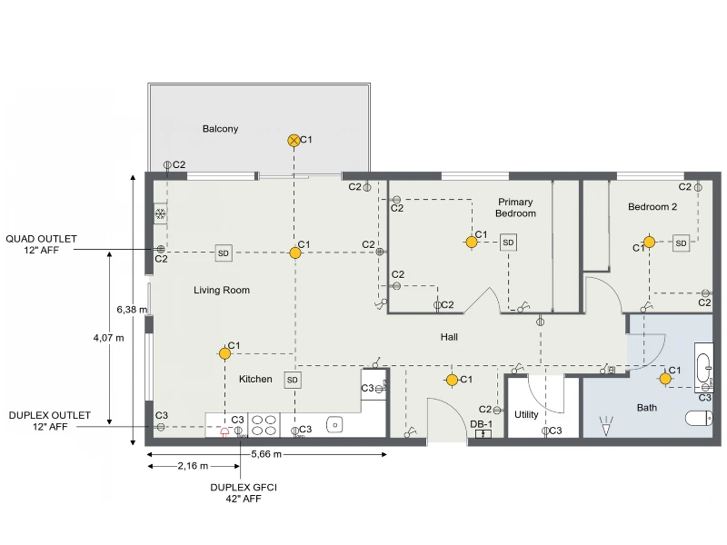

Quick summary:
To read an electrical floor plan, start with the title block and legend, then review the drawing one category at a time. Identify the lighting, switches, outlets, panels, circuits, and special systems in each room. Since symbols can vary between plans, always check the legend and ask an electrician or designer about anything that is unclear.
Electrical floor plans can look intimidating at first. There are symbols everywhere, lines running across rooms, and labels that seem impossible to decode.
But once you understand the basic system, reading a plan becomes much easier.
In this guide, we’ll walk through the most common elements you’ll see on an electrical floor plan, what the symbols mean, and how to approach a drawing without getting overwhelmed.

Start With the Title Block and Legend
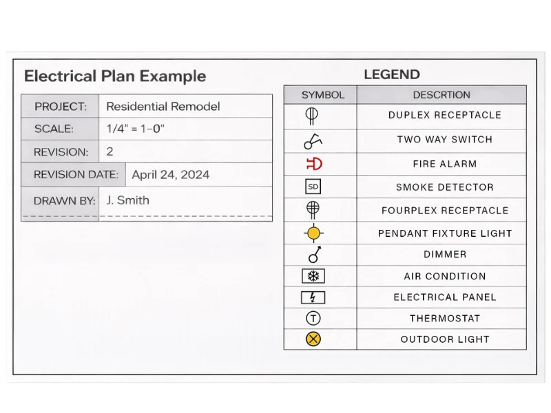
Before looking at the electrical symbols themselves, take a moment to orient yourself.
Most plans include a title block, usually placed in one of the corners of the drawing. This section tells you important information like:
- Project name
- Drawing scale
- Revision date
- Sheet number
This helps confirm exactly what you’re looking at and whether you’re working from the latest version.
You may also see a legend, sometimes called a key. This explains the symbols used throughout the drawing.
Electrical symbols are not always universal. Different countries, firms, architects, and electricians may use slightly different conventions, so checking the legend can save a lot of confusion later.
Once you understand the project and the symbols being used, you can start reading the actual layout.
The Five Main Things to Look For
When reading an electrical floor plan, there are five major categories you’ll usually scan for:
- Lighting
- Switches
- Outlets
- Panels and circuits
- Special systems
Working through the drawing in this order makes the plan much easier to understand.
1. Lighting symbols
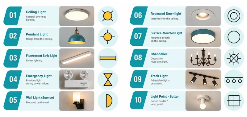
Lighting fixtures are usually the easiest elements to spot on a plan.
They are commonly shown as circles, often with additional lines, crosses, or markings inside them. Different symbols represent different fixture types, including:
- Ceiling lights
- Recessed downlights
- Pendant lights
- Wall-mounted fixtures
- Surface-mounted fixtures
Some plans use color coding to make lighting easier to identify, while others stay entirely black and white.
One important thing to remember: the symbol itself usually does not tell you details like bulb type or wattage. That information is normally listed separately in a fixture schedule.
Recommended read: how to make a lighting plan in 7 steps
2. Switch symbols
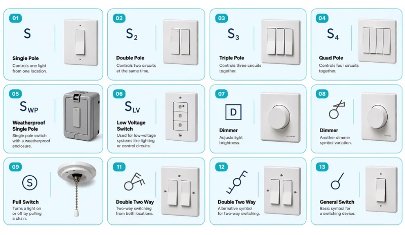
Switches show where lights or electrical devices are controlled from.
Unlike lighting symbols, switches are often letter-based. For example:
- S usually means a single-pole switch
- S3 may indicate a triple-pole switch
- SLV can represent a low-voltage switch
Some plans combine letters with circles or lines depending on the switch type.
Because abbreviations vary between drawings, always double-check the legend if something is unclear.
3. Outlet symbols
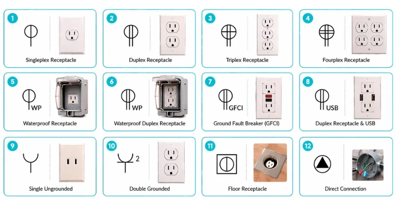
Outlets are commonly shown as circles with vertical lines.
In many plans:
- One vertical line represents a single outlet
- Two vertical lines represent a duplex outlet, the standard double outlet found in most homes
Additional letters may provide more detail.
For example:
- USB may indicate built-in USB charging ports
- Other abbreviations can identify dedicated circuits, floor outlets, or special power requirements
Again, the legend is your best reference for understanding these details.
4. Panels and distribution boards
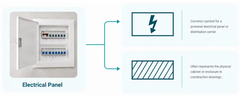
Panels and distribution boards are the central hubs where electrical circuits originate.
These are usually drawn as labeled rectangles with names like:
- Panel A
- DB-1
- Main Panel
From there, lines extend outward to lights, switches, and outlets throughout the space.
Devices connected to the same circuit often share matching labels or numbers, such as:
- C3
- L2
- Circuit 5
This becomes especially useful when troubleshooting, understanding load distribution, or identifying which outlets are connected to the same breaker.
5. Special systems

Modern electrical plans often include systems beyond standard lighting and power.
These may include:
- Smoke detectors
- Fire alarms
- Security cameras
- Intercom systems
- Data and network points
- Access control systems
Every project handles these differently, so special symbols vary widely from one drawing to another.
This is another area where checking the legend becomes important.
Understanding Wiring Lines
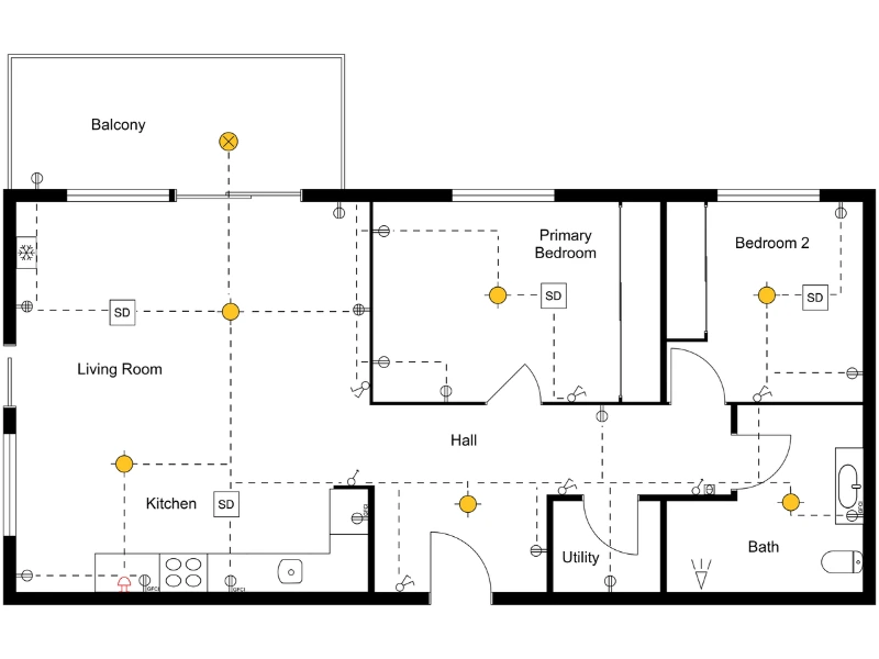
Some electrical plans also show simplified wiring paths.
These lines do not usually represent the exact route wiring takes inside walls or ceilings. Instead, they show general connections between components and help explain how electricity flows through the space.
Think of them as a simplified map of the electrical system rather than a literal installation guide.
Tips for Reading Electrical Floor Plans
If you’re new to reading plans, a few simple habits can make the process much easier.
Work one room at a time
Avoid trying to understand the entire drawing at once.
Focus on a single room or zone first, then move through the project systematically.
Cross-reference other drawings
Electrical plans make more sense when viewed alongside architectural floor plans.
Looking at both together helps you understand the purpose of each room and how the electrical layout supports the space.
Mark anything unclear
Even experienced professionals ask questions when reviewing plans.
If a symbol or connection does not make sense, circle it and review it with the electrician, architect, or designer before work begins.
Final Thoughts
Reading an electrical floor plan is mostly about learning the symbols and following the connections.
At first, the drawings can feel crowded and confusing. But once you understand how lighting, switches, outlets, circuits, and special systems are represented, the layout becomes much easier to interpret.
The key is to work methodically, focus on one area at a time, and use the legend whenever you’re unsure.
Over time, the symbols stop looking random, and start telling a clear story about how the space functions electrically.
Create Your Own Electrical Floor Plan
Now that you know how to read an electrical floor plan, you can start planning your own. With RoomSketcher’s electrical drawing software, you can create the floor plan first, then add outlets, switches, lighting, safety symbols, and other electrical details using more than 250 ready-made symbols.
You can update the layout as your project develops, keep different plan versions organized, and share the finished plan with a contractor, client, or project partner. No CAD experience is needed.
Related Articles
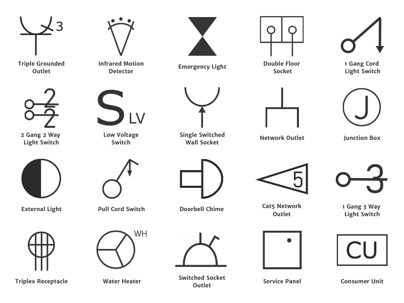
Complete Guide to Electrical Symbols and Abbreviations
What are electrical symbols, and what do they mean? Where are they placed on a floor plan, and what are the regulations for placing them? Here's everything you need to know about electrical plans.
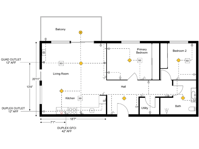
How to Draw an Electrical Plan with RoomSketcher
Learn how to draw an electrical plan step by step. This guide shows how to place lighting, outlets, and switches clearly on your floor plan so the layout is easy to understand and share.
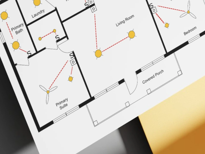
How to Create a Reflected Ceiling Plan
A reflected ceiling plan helps you organize everything that happens above a room. It shows where lighting, ventilation, and other ceiling elements should be placed so the layout works both visually and technically.